
Robert Knott & Stephen Lilley
Earthing system design for 11kV high voltage (HV) substations in developed, industrial or urban areas can prove challenging, particularly where the availability of land for the placement of buried conductor is scarce. In this article, PSC unpacks the typical challenges with these projects and the actions that are available to achieve a compliant[1] and safe system.
Challenges
As mentioned previously, one of the main challenges of earthing system design in these areas is identifying suitable land for the installation of bare buried earth conductors, which can impact the safety of people around an HV substation during an earth fault and ensure compliance with current density regulations1.
Challenges can also be presented with conducting soil resistivity measurements, when typically, up to 200m of land (free of buried services) is required to complete the pre-construction tests. The results of these measurements are a critical piece of data supporting the analysis of a proposed earthing system design and greatly influence the outcomes of a calculation study. The lack of available land on or surrounding the proposed development to conduct the soil resistivity measurements is a common issue leading to compromises on the test locations.
The issue of land availability and its impact can also be compounded where part of the supply arrangement to the proposed substation includes an unearthed overhead line section. This can either limit the amount of fault current that returns to the source via cable sheaths or ensure that the full fault current returns to the source through the ground. In either scenario, the immediate effect is that a higher earth potential rise (EPR) will be experienced at the new substation.
Actions for a safe site

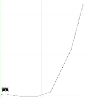
Figure 1 – Radial Electrode example
Where compromises have been made on the soil resistivity measurements locations, or there are concerns over the results of the measurements, further tests, such as a fall of potential (FOP) measurement of the existing electricity network, could be conducted to determine the network resistance contribution to the proposed HV substation.
Should an FOP not be feasible due to similar issues with regard to the lack of available/suitable land, modeling the electricity network as part of the earthing system simulation studies will provide an estimate of the resistance contribution ‘seen’ from the proposed earthing system.
These actions will support a more accurate determination of the EPR and associated safety voltages at the proposed substation.
In addition to these actions, the excavation of the cable route to the supply substation or overhead line point of connection can be taken advantage of to install additional radial electrodes as shown in the adjacent figure. This is a proven and cost-efficient method to reduce the earthing system resistance ‘seen’ at a proposed substation and achieve compliance with current density regulations1, where suitable land is not available.
Where these challenges are presented, it is crucial that a bespoke earthing system design study is undertaken by experienced consultants to provide safe systems and evaluate all available design options.
PSC can help

Figure 2 – CDEGS Touch Voltage Plot
PSC utilizes extensive industry experience to support our clients to accurately analyze and design bespoke HV earthing systems for their installations utilizing the world-leading CDEGS modeling software that adheres to industry standards.
PSC has developed effective modeling and analysis techniques to provide customized, safe and compliant earthing system designs efficiently.
We aim to support clients from pre-construction through any project’s design process and post-construction commissioning phases.
Learn more about our capability in this area or contact us to find out how we can help.
References
[1] ENA TS 41-24, Guidelines for the design, installation, testing and maintenance of main earthing systems in substations
