
Jenny Zhou & Iman Kaffashan
Running the grid smoothly is a delicate and complex task. Among the countless steps that enable a consistent and reliable flow of electricity is regulating the voltage. Although, surges from switching or lightning strikes threaten substation processes. To mitigate these issues, surge arresters are used to limit the overvoltage and absorb excess energy. However, knowing which arresters to use and where to place them is of critical importance. EMT-type detailed design studies can help ensure the acquisition of the correct equipment and knowing where to install it.
This blog highlights some key aspects and benefits of EMT-type detailed design studies and substation insulation coordination.
Insulation Coordination Overview
Insulation coordination ensures the equipment has the dielectric strength to withstand expected overvoltages. It provides substation designers with the necessary data that to safeguard effectively against insulation failures like flashovers or breakdowns caused by atmospheric and switching surges. EMT-type detailed design studies offer a comprehensive approach to evaluating transient overvoltages. The simulations capture the complex behavior of the system and account for phenomena like wave propagation, reflections, and electromagnetic interference, allowing engineers to accurately predict the electrical stress on the insulation and evaluate its adequacy.
Surge Arresters
Surge arresters are among the best solutions for controlling and reducing overvoltages. However, selecting the proper surge arresters (absorption capabilities) and installing them in the right location is critical.
The insulation strength of equipment for lightning and switching stresses depends on the predicted overvoltages. There needs to be an adequate margin between the maximum overvoltage to be expected (corresponding to the switching impulse protective level SIPL and the lightning impulse protective level LIPL), the switching impulse SIWL, and lightning impulse withstand levels LIWL. The minimum margins are determined by standards like IEEE C62, IEC 60071, and customer specifications.
Conducting Studies for Substations
EMT-type detailed design studies use EMT simulation tools like PSCAD to model and analyze the behavior of substation insulation under various conditions. These studies consider factors like lightning strikes, switching operations, and faults that can induce transient overvoltages.
Switching Overvoltage (SOV)
SOV evaluations encompass line energization, reclosing energization, and fault-clearing events. For line energization and reclosing, the expected statistical switching overvoltages are evaluated by applying statistical random breaker closings in each energization case. Fault clearing events consist of applying point-on-wave fault application in the simulation and clearing different types of faults at various locations such as both ends of lines, transposition points, both sides of the series capacitor, etc.
The IEC 60071-2 standard [1] specifies a minimum safety margin of 15% to 20% (depending on normal operating voltage range) for switching surges, between basic switching impulse insulation level (BSL), and switching protection level (SPL) of the arrester. The required switching impulse level (RSWIL) is obtained by applying the recommended safety factor (), coordination factor (), and the altitude correction factor () to the calculated worst-case switching overvoltage. Lastly, RSWIL is compared against the basic insulation level (BIL) to calculate the available protective margin.
Lightning Overvoltage (LOV)
Lightning frequencies are considered fast front transients in power systems because they cover a high-frequency range (10 kHz up to 1 MHz). LOVs can result from a ‘direct strike’ to a phase conductor (shielding failure) or due to ‘back flashover’ resulting from a lightning strike on a shielding (ground) wire. Both events cause transient voltage escalations at the terminals of station equipment.
For the LOV model development, overhead transmission lines, conductors, and ground wires are modeled as the frequency-dependent model up to 5 spans out and terminated by their surge impedance. Additionally, tower structures are modeled as a vertical single conductor reflecting the wave transmission line terminated by a tower footing resistance. The tower insulators are represented by voltage-dependent flashover switches in parallel with capacitors connected between the respective phases and poles. Substation equipment like circuit breakers and disconnect switches are represented by their stray capacitances according to IEEE Std C37.011. To represent surge arresters, the fast front model, based on the standard technique proposed by IEEE Std. C62.22, is considered. The protective margin between RLIWV and BIL shouldn’t be less than 20%. Moreover, the estimated surge arrester’s dissipated energy should also remain within the arrester’s energy capability.
Insulation Coordination
By considering the maximum continuous overvoltage (MCOV), switching surge type overvoltage (SOV), and lightning surge type overvoltage (LOV), the overall substation insulation coordination is to coordinate and state the requirements on insulation levels of the main equipment, and to specify the data and duties of all arresters.
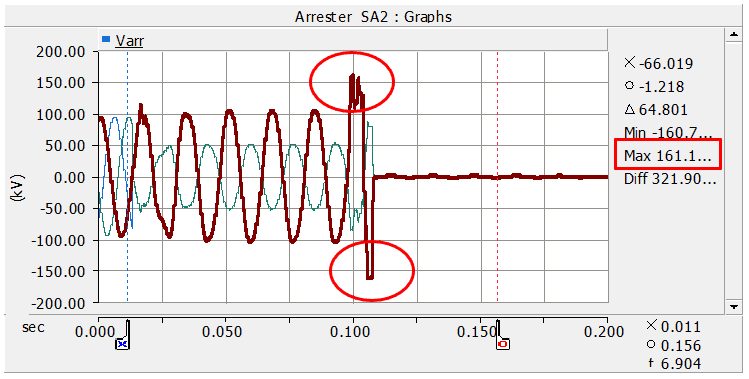
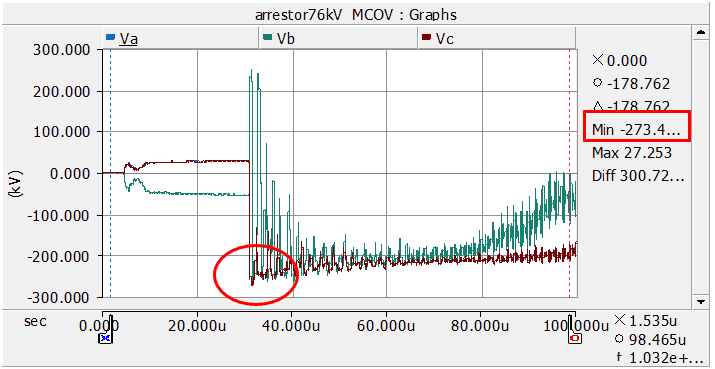
In a sample SOV and LOV case study performed for a 115 kV substation, the EMT simulation software PSCAD was used to identify the severity of potential voltage surges affecting the electrical equipment in the substation. The waveform for the SOV and LOV assessment of the worst-case scenario of the case study are depicted in Figure 1 and Figure 2, respectively. The available protective margin is calculated and reported in Table I.

Figure 1 Max Overvoltage –SOV_worst Scenario for the Case Study (Line-to-Line Fault Applied)

Figure 2 Max Overvoltage –LOV_worst Scenario for the Case Study

Table I SOV_worst and LOV_worst Results for a Sample Case Study
As summarized in Table I, it was found that the switching overvoltage and the lightning overvoltages were within the limits and the insulation levels of the main equipment have adequate available protective margins. Moreover, the surge arrester energy discharge levels determined for selected surge arresters in the substation were within the manufacturer’s energy discharge ratings for all switching and lightning strike events studied; therefore, planned insulation strengths and the surge arrester ratings appear to be adequate for the substation equipment.
Why Utilities need EMT-type detailed design studies
EMT-type detailed design studies offer a comprehensive evaluation of insulation performance and play a crucial role in designing robust and reliable systems. Firstly, they provide a more realistic assessment of insulation performance compared to simplified analytical methods. This makes identifying potential insulation stress points, weak spots, and overvoltage magnitudes more accurate. These studies also aid in selecting appropriate insulation levels and protective devices to mitigate risks effectively. What’s more, EMT-type studies allow for the evaluation of different insulation configurations, helping optimize design choices and reduce costs. Finally, they enable engineers to investigate the effects of system upgrades or modifications on insulation performance, ensuring a smooth and reliable transition.
By leveraging advanced electromagnetic transient analysis techniques, utilities can optimize insulation design, select appropriate protective devices, and mitigate insulation failures effectively, ultimately contributing to the enhanced performance and longevity of substations.
Related content: Check out this blog post by author’s Jenny Zhou and Iman Kaffashan, “Reliable by design: The power of EMT-type design studies for offshore wind substation development.“
Ensuring that the equipment you’re using has the capacity to protect your assets is vital. The experts at PSC can simulate EMT-type detailed design studies and help you find a cost-effective solution for your grid.
References
[1] IEC 60071-2, Insulation co-ordination – Part 2: Application guide. 2018-03.
[2] “IEEE Guide for the Application of Metal-Oxide Surge Arresters for Alternating-Current Systems,” in IEEE Std C62.22-2009 (Revision of IEEE Std C62.22-1997), vol., no., pp.1-142, 3 July 2009.
[3] IEEE Guide for the Application of Insulation Coordination, in IEEE Std 1313.2-1999, vol., no., pp. 1-68, 15 Nov. 1999.
