Every power system needs some form of reactive power support to maintain system reliability and to counter disturbances that may lead to a drop in voltage. Voltage stability is a key limitation to the enhanced integration of renewable energy sources into the electricity grid. Thus, choosing the most appropriate solutions and siting them in the most efficient locations is a key skill for any power system engineer. This blog post looks at some of the important considerations to bear in mind.
The growing need for reactive power compensation
With the growing prevalence of power systems that incorporate intermittent renewable energy sources, reactive power compensation is essential to ensure that the system is stable and operates within required stability limits. These limits usually form part of the Grid Code that applies to the system. Without reactive power compensation, voltages may collapse completely, resulting in a total blackout if the cascading events are not properly mitigated. A healthy voltage profile also limits the transmission losses and the amount of current drawn by constant power loads such as motors, thus preventing the overloading of electrical networks.
A choice of technologies
This raises the question of how to choose and deploy reactive power compensation to optimize the operation of the power system. The choice includes static resources like switched capacitor banks and dynamic resources such as synchronous condensers, Static VAR Compensators (SVCs), Static Synchronous Compensators (STATCOMs) etc.[1]. Each power system needs to be assessed individually to ensure the right compensators are deployed in the most appropriate place.
Switched capacitor banks, for example, are a cost-effective solution typically used in distribution systems to alleviate low voltage conditions. They are located close to inductive loads to counteract any lagging power factor. However, these banks are unable to provide dynamic support after a contingency. Thus, the optimal placement of these banks is usually at the end of long feeders or near large industrial loads where reactive power demand is likely to be high.
Synchronous condensers, Static VAR Compensators (SVC) or Static Synchronous Compensators (STATCOM) provide leading or lagging reactive power as needed. They can quickly adjust their output to stabilize voltage, which makes them suitable for providing rapid and dynamic support. Synchronous condensers are costly, albeit they do offer inertial support in conditions where the system strength is low, or the grid is weak. Within power electronic devices, STATCOM’s provide faster response and better voltage support in low-voltage conditions than SVC’s but are more expensive to install.
Therefore, understanding the equipment choices available for reactive power compensation design is only part of the story and careful consideration must be given to the optimal placement of this equipment to ensure the most effective utilization.
Optimal deployment
It may be noted that since reactive power transfer depends on voltage difference, it cannot be transferred over long distances like real power and must be supplied locally[2]. Therefore, determining the optimal location for a reactive power compensation solution is an optimization problem whose aim is to enhance the network voltage profile, minimize power losses, and improve voltage stability limits for different operating scenarios such as N-1 contingency, variation in generation and load, load growth and other challenges.
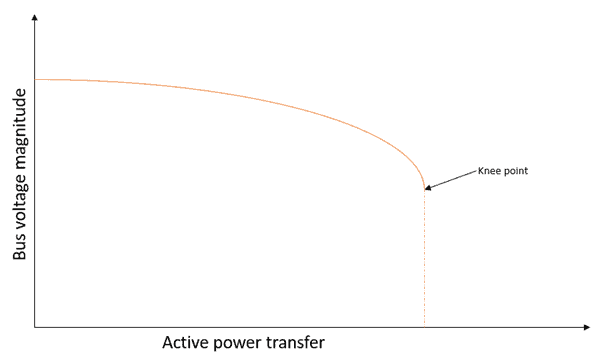
Steady state analysis is carried out as the first step using PV and QV curves[3]. PV curves are used as a screening tool to assess the voltage stability margin and identify the weakest buses in the power system under various contingencies. It involves monitoring of the bus voltages as the real power transfer increases. The knee-point of the curve is the maximum power transfer point and the steady state voltage stability limit, beyond which the load flow calculation diverges.

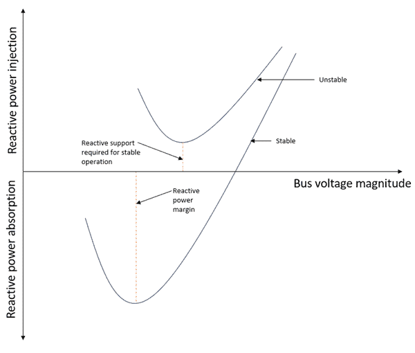
Subsequently, QV curves are analyzed to determine the amount of reactive compensation required at the weakest buses for the most severe contingencies identified through PV curves. A fictitious synchronous condenser is considered at a bus, and its voltage set point is reduced while monitoring the reactive power injected. The point at which dQ/dV becomes zero is the voltage stability limit, which represents the maximum allowable increase in reactive power for a stable system. If the reactive power injected never becomes zero, the system is unstable, and the QV curve gives the minimum amount of reactive power required for stable operation.

Alternatively, heuristic-based approaches and Monte Carlo simulations can be utilized in large power systems under different operating conditions to solve the non-linear, mixed-integer, constrained optimization problem to identify severe contingencies and weak buses in the network using voltage stability indices[4]. These buses are chosen for optimal placement of reactive power compensation.
Furthermore, time domain analysis may be required to assess the transient voltage stability after severe contingencies1. Voltage dips are usually a result of power swings as the grid responds to a major event and severe faults, which lead to a stalling of induction motors, leading to an increase in the reactive power demand. By monitoring the voltage dips and damping of oscillations after a disturbance, time domain analysis helps to identify the buses that need reactive support so that the transient voltage response criteria of the utility is satisfied.
Cost benefits
The benefits of an effective and optimal place of reactive power compensation resources go beyond the technical advantages of helping to ensure a stable and reliable power system. It also positively impacts capital and operating expenditure budgets by minimizing the amount of reactive compensation required and the operating losses, respectively[5].
How PSC can help
PSC utilizes its extensive industry experience to support our clients in accurately assessing the optimal placement of reactive power compensation within power systems based on any required voltage stability limits for ensuring Grid Code compliance.
Find out more about our DER capabilities and contact us to talk about first steps.
References
[1] https://www.nerc.com/comm/RSTC_Reliability_Guidelines/Reliability%20Guideline%20-%20Reactive%20Power%20Planning.pdf
[2] https://www.nationalgrideso.com/industry-information/balancing-services/reactive-power-services
[3] https://www.e-cigre.org/publications/detail/024-planning-against-voltage-collapse.html
[4] https://ieeexplore.ieee.org/stamp/stamp.jsp?tp=&arnumber=9288663
[5] https://www.e-cigre.org/publications/detail/030-reactive-power-compensation-analyses-and-planning-procedure.html

